One of the fun things about being on a rover team is it gives me an opportunity to play with hardware far out of what I’d normally encounter. Much of that falls in the category of power, as we design for about a kW of draw running on 12V (for now).
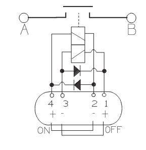
A feature of our emergency stop system is a pair of 260A automotive relays, which I recently fried. While disappointed to have ruined a rather expensive relay, I was excited to take it apart. Pictures below, and after that an explanation of what went wrong.
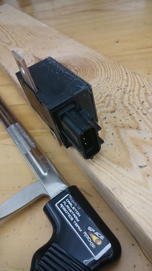
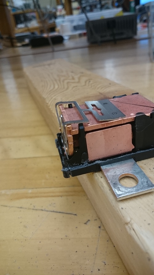
My Tool of Choice
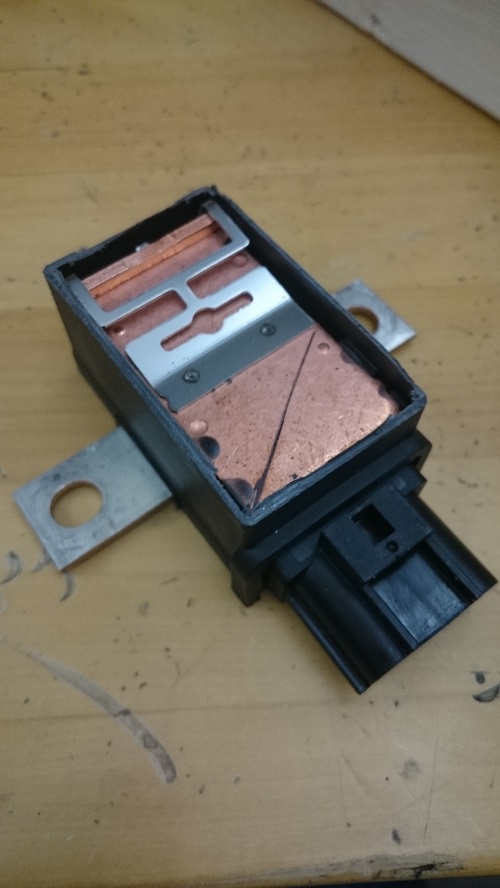
Top Off. Lots of Copper Here
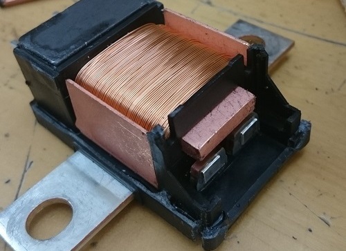
Sides off. The far left copper is actuated by the coil, and the top metal acts as the spring. It's bistable, so the copper stays where you left it after removing coil voltage
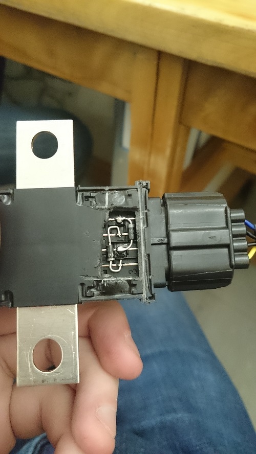
The back, with contacts. Note the copper core in the coil. Did I mention it takes 3 amps to switch?
So, what went wrong?
Well that was easy.